Have you ever been in a car or truck and the ride was so smooth (despite potholes, bumps, etc.) you fell asleep almost immediately?
That’s what you get when your vehicle has a great suspension system. My husband and I share a love-hate relationship when we travel long distances for that reason.
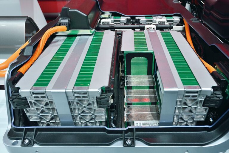
He’ll be out like a bulb when we use our hybrid while I’m driving. There are five types of suspension systems, and three main components.
Take my word for it, that’s something you should focus on when purchasing your truck or car.
What are the Different Types of Suspension Systems?
There are five types of suspension: MacPherson Strut, Short/Long Arm, Double Wishbone, Dual Beam, and Beam Axle.
There are three different types of vehicle suspension components: shock absorbers, springs, and linkages. All of a vehicle’s suspension components are held in place by its connections.
The vehicle is protected from disturbances and holes along the roadway by springs. Hydraulic pistons, as well as cylinders, are used shock absorbers to mitigate the vehicle’s stress loads.
In addition, they help to reduce spring oscillations, allowing the vehicle to return to a stable position more quickly after being hit by an object on the street.
1. Shock Absorbers

Hydraulic fluid flows through a piston and cylinder to modulate the damping force in the jounce (retraction) and expand (rebound) locations of the suspension system.
Shock absorbers are programmed to withdraw rather than extend when applied with a force less than their set threshold.
To improve the vehicle’s ride and handling, this action curtails the spring oscillations but also absorbs the force of the road bumps.
2. Links

Diverse suspension systems use a combination of different-shaped links. Fabricated, molded, as well as stamped metal forms are available in a variety of shapes and sizes to support springs, shocks, as well as wheels on the vehicle’s chassis.
Simple linkages are those that connect two wheels on opposite sides of a vehicle using a straight bar. Others can be sculpted to link springs, shock absorbers, as well as wheels to automobiles.
3. Springs

These suspension systems employ three different spring types: coil, leaf, and torsion bar. Wound torsion bars are all that coil springs are. It is standard practice to utilize them because they are small, easy to mount and have a great life expectancy.
Long, thin leaf springs are loaded in bending. To achieve the correct spring rate, they are employed as an assembly of multiple thin metal layers.
Leaf springs perform double duty as a dampening element and a linkage in a bicycle suspension system.
As the name suggests, torsion bars use a long twisting bar to lessen automotive shock loading. It is more challenging to bundle a car’s torsion bars than other parts.
Suspension systems fall into two categories:
Dependent Suspension
There are two types of springs used in the suspension system: coil springs and leaf springs. In addition to the wheel, the system includes links/arms and shock absorbers.
A coil and spring connected to the wheel is the simplest design, although there are several more complex configurations. Dependent and independent suspension systems are the two most common types of suspension systems.
The term “dependent suspension system” refers to the fact that the left and right wheels are linked by a beam or axle. Leaf springs and shock absorbers or coil springs and shock absorbers can be used to spring this type of suspension.
To use it in mass-market automobiles that need both endurance and price, manufacturers must use a simple structure.
1. Beam Axle

Rear-drive automobiles’ front axles used to be made of solid beams. The entire front end of the vehicle was connected to the two steerable wheels by a single, fixed, continuous element.
Because the two wheels are mechanically linked, this suspension arrangement is referred to as “dependent.” A solid beam axle spanning the whole width of the vehicle connected the two wheels of the first Model T passenger cars, which were rear-driven.
An I-beam steel axle with machined ends was used to allow vertically placed kingpins to be attached to the axle, allowing the vehicle to be steered.
A semi-elliptical reversed leaf spring gets fitted between the axle and the car’s body to reduce the vehicle’s rough ride.
Each of the leaf spring’s two lower curving ends was attached to the axle, while the upper middle part was attached directly to the car’s frame in two closely separated spots.
Vehicles like the Model T, which used a solid beam axle, can also use a drive axle assembly as its solid beam component between the two driving wheels.
Power is delivered to the drive axle via the driveshaft, where it is turned 90 degrees before being routed to the automobile’s wheels via the drive axle’s mechanical components.
Power is transferred from the vehicle’s drive shaft to a component known as the carrier by the first gear set. In the carrier, the “differential” is kept safe and sound.
Each driving wheel receives the same amount of power regardless of its rotational speed, as is the case when driving around a corner.
When it comes to four-wheel-drive cars, drive axles have historically been employed on the back wheels and the front for all-wheel-drive vehicles.
With the advent of front-wheel drive automobiles, which combine the transmission with the driving axle, the term “transaxle” has gained currency.
Pros and Cons
Solid beam axles have the benefits of simplicity and strength. During vertical travel, the wheel is held nearly perpendicular to the road, allowing for precise control of the wheel camber.
Keeping the wheels at a 90-degree angle to the pavement is especially beneficial for trucks hauling heavy loads.
In comparison to other suspension systems, solid beam axles have the disadvantage of not being able to alter camber during hard turning to keep the wheels off their sides and securely in grip with the ground.
Another drawback of this design is that when one of the wheels hits a rock or hole in the roadway, a shock wave propagates across the vehicle’s whole rear (or front), passengers may feel uncomfortable and perhaps “shimmy” as a result.
Additionally, a car with solid beam axles has a higher sprung weight, resulting in a rougher ride and greater passenger misery.
2. Dual‐Beam Suspension

Light vehicles with a dual-beam front suspension are popular with US automakers. A “separate” suspension system is one where the wheels don’t directly attach to each other, like a solid beam suspension.
Pros and Cons
With the dual-beam suspension, frontal shock loads from ground inconsistencies can be localized to the area where they occur.
One-piece front beam suspensions, wherein shock loads are transferred from one wheel to another, result in high body impact load as well as unpleasantness for the driver and passengers.
Dual-beam front suspensions have the drawback of causing the sides of tires to get worn, plus wheel scrubbing due to the wheel camber shifting when the car goes vertically.
The U.S. carmakers use dual-beam suspension arms that overlay one another as long as possible to minimize the above-mentioned drawbacks in light vehicles.
Independent Suspension Systems
An Independent Suspension is where the two wheels do not directly connect, in other words, the opposite of a dependent suspension system.
1. MacPherson Strut Suspension

It was in 1947 that American automotive engineer Earle S. Macpherson created this suspension. The Macpherson strut suspension weighs less than a beam, plus it falls into the same price range as the short/long-arm suspension.
It gained prominence in the 1970s as state legislation that requires more fuel-efficient functioning led to the widespread adoption of lighter, front-drive automobiles.
Similar to the short/longarm, however, with the upper arm rotated 90 degrees up as well as outboard toward a near-vertical angle, the long member replaces the MacPherson strut suspension.
Pros and Cons
An anti-friction thrust bearing sits at the top of the strut, which houses a spring as well as a shock absorber.
Fully connected to a body structure on top and the knuckle beneath, this is a typical use. For steering, it spins with the wheel on an upper bearing while supporting vertically imposed suspension stresses.
Like short/long-arm suspension systems, it aids in vehicle cornering camber control, but because the strut’s length and mounting angle differ from the SLA’s short upper arm, it does not do so during full jounce.
A transversely positioned engine and driveshaft can only be installed in front-drive cars with the upper arm assembly rotated up and outboard.
Both longitudinal and lateral assistance for the wheel is provided by a comparable lower wishbone-shaped connection in the design.
Several automobiles employ struts in the back suspension as well. On account of the lack of steerability, it lacks the anti-friction bearing on top as the front strut does.
2. Double Wishbone Suspension

In Europe in the 1930s and in Detroit in 1935, that suspension was initially deployed. The MacPherson strut, a variant of the double-wishbone suspension, became widely employed in the 1970s when front-wheel-drive cars were introduced.
The Double-wishbone setup has been utilized as a replacement for the dependent suspension systems in the past. It comprises two identically sized wishbone-shaped arms that are stacked on top of each other.
For steering, the closed ends of both wishbone arms get attached to the vehicle, knuckles at the top as well as the bottom. The wheel spindle or hub is supported by the vehicle’s knuckle. Each wishbone member has two open ends that get hinged to the vehicle’s frame.
When a drive-wheel application makes use of the double-wishbone suspension, a coil spring is mounted on the upper arm’s center component and extends upward to be supported by a body member.
The upper arm bears the bulk of the vertical load, while the vehicle’s driveshaft can be stowed below.
Double-wishbone suspensions are utilized in non-drive wheel applications, with a coil spring located in the mid-section of the lower arm then extending upward to a body support component.
Pros and Cons
Wishbone suspensions are more expensive than beam-type suspensions, but they are also smaller and less rigid. This is because the wishbone links are more complexly formed and have six attachment locations instead of only two for the heavy beam form of suspension.
Both suspension methods align the wheels perpendicular to the road, which gives them an edge over others.
As previously said, it causes tire edge wear and wheel scouring on the road surface, but on particular cars, as will be detailed later, the closely controlled camber adjustment with suspension travel might be advantageous.
The toe, carpet, and camber angles of a double-wishbone suspension system can all be adjusted during suspension travel.
3. Short/Long Arm Suspension

It is a variation of the double-wishbone suspension, which could be utilized on both the front and back wheels of automobiles.
Both arms are the same length when suspended by a double-wishbone. An SLA suspension has two arms that are not similar in length; one is shorter than the next.
Unlike the solid beam style of suspension, the short/long-arm suspension is regarded as independent because it does not directly link the wheels.
The knuckle that holds the spindle to which the wheel is fastened is connected to the closed side of both the lower and upper wishbone components.
A swiveling joint is used for both arm-to-knuckle connections so that the vehicle can be steered. For wheel up-and-down movements, the rubberized joints on both arms’ inboard end attach to an automotive structural part.
When a car is rounding a bend, this design helps keep the camber under control and the tire edges from wearing out.
As a result of reducing the upper arm’s length, this suspension system helps return the contact pattern of both wheels to the middle of the tire during cornering, when gravitational force tends to roll the car.
As long as the effect continues to full jounce, it’s a great choice for high-performance cars. On the lower arm for non-drive wheel systems, a coaxial spring and shock absorber can be installed. For drive wheel installations, it’s on the upper arm.
Pros and Cons
The Macpherson Strut suspension weighs and costs about the same as the Strut.
There is less capacity for the engine that’s transversely mounted as well as the front driveshaft that is popular in modern fuel-efficient cars when using the Macpherson strut.
That’s because it takes up more useful space. Rear-drive vehicles with a front-mounted inline engine are the most appropriate applications for this wheel design.